P-01 of P-05
Airport Off-Grid Charging System
Landscaping robots · full mechanical design
An off-grid, solar-powered charging station that keeps autonomous landscaping robots running at airports and large grounds. I lead the full mechanical design of the second generation: internal packaging, thermal CFD, structural FEA, and design to IP54 and UL 2743.
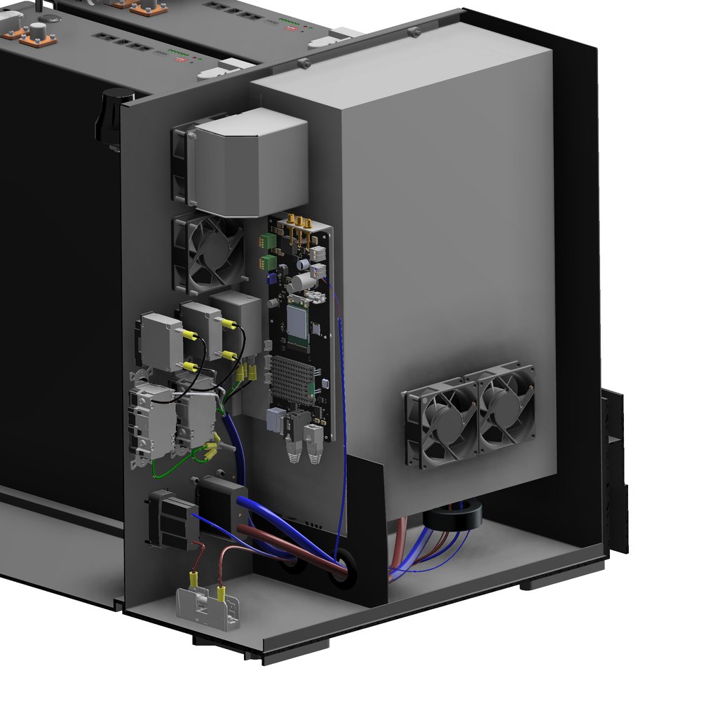
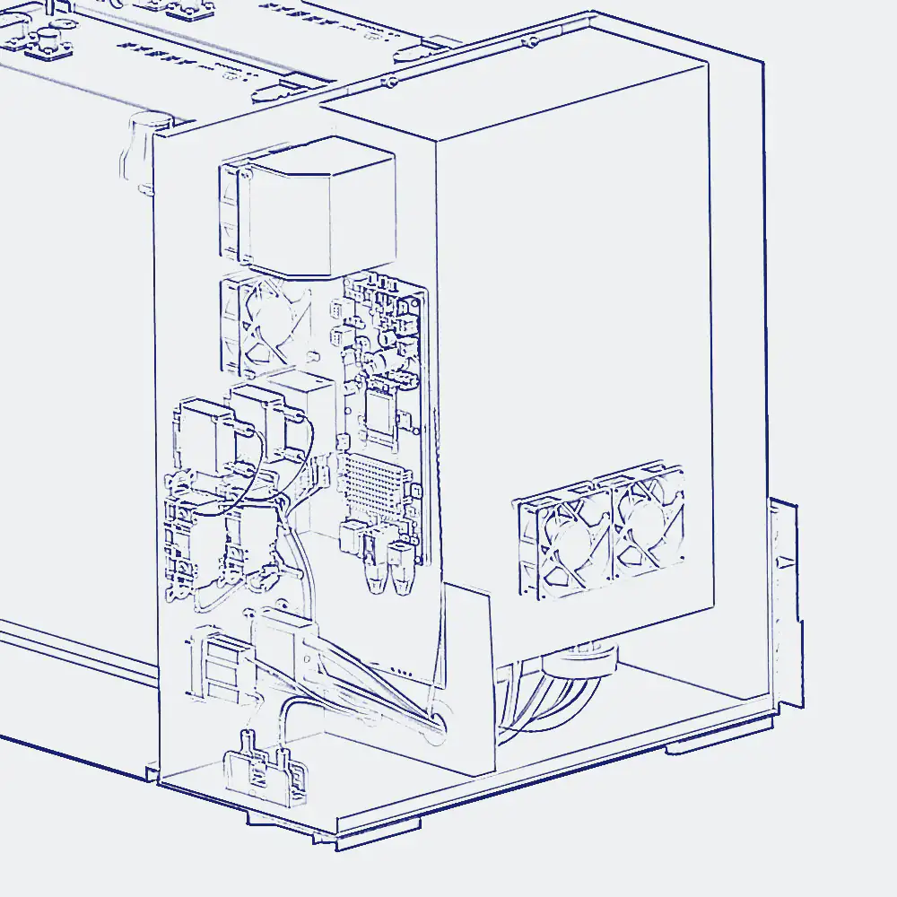
Section A-A, The system
Off-grid power for autonomous groundskeeping
An off-grid, solar-powered charging station that keeps autonomous landscaping and mowing robots running at airports and other large grounds, far from mains power. I lead the full mechanical design of the second generation, targeting IP54 ingress protection, UL 2743, and roughly 3600 W of off-grid output.
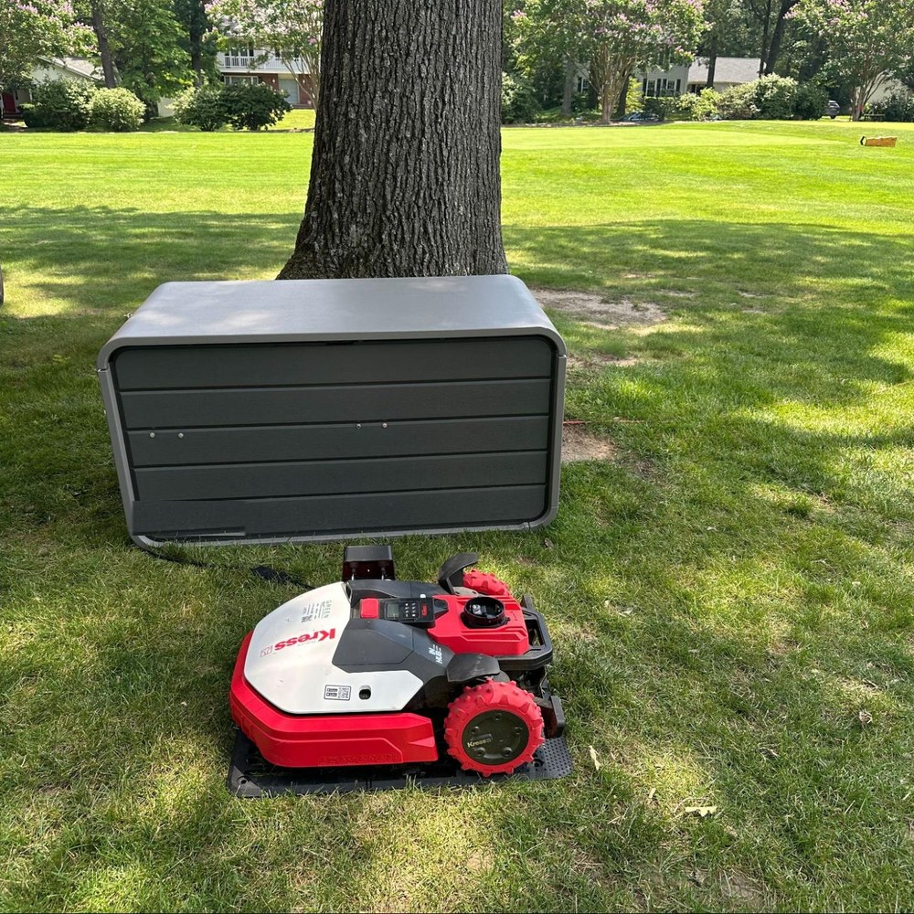
Section B-B, First generation
A field-tested prototype
The first generation proved the concept in the field: an off-grid unit charging a robotic mower on site. It validated the idea and surfaced exactly what the next version needed, more ruggedness, better sealing, thermal headroom, and simpler assembly.
Section C-C, Second generation
A rugged, integrated redesign
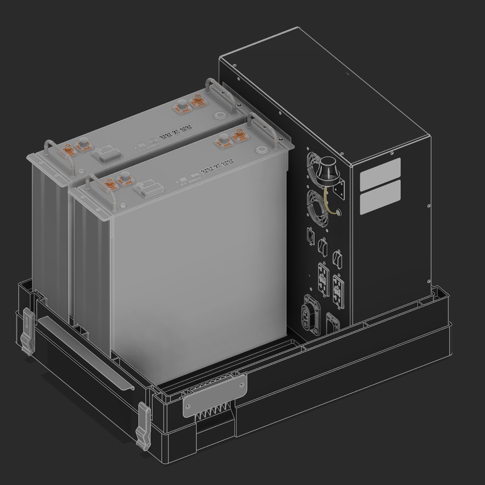
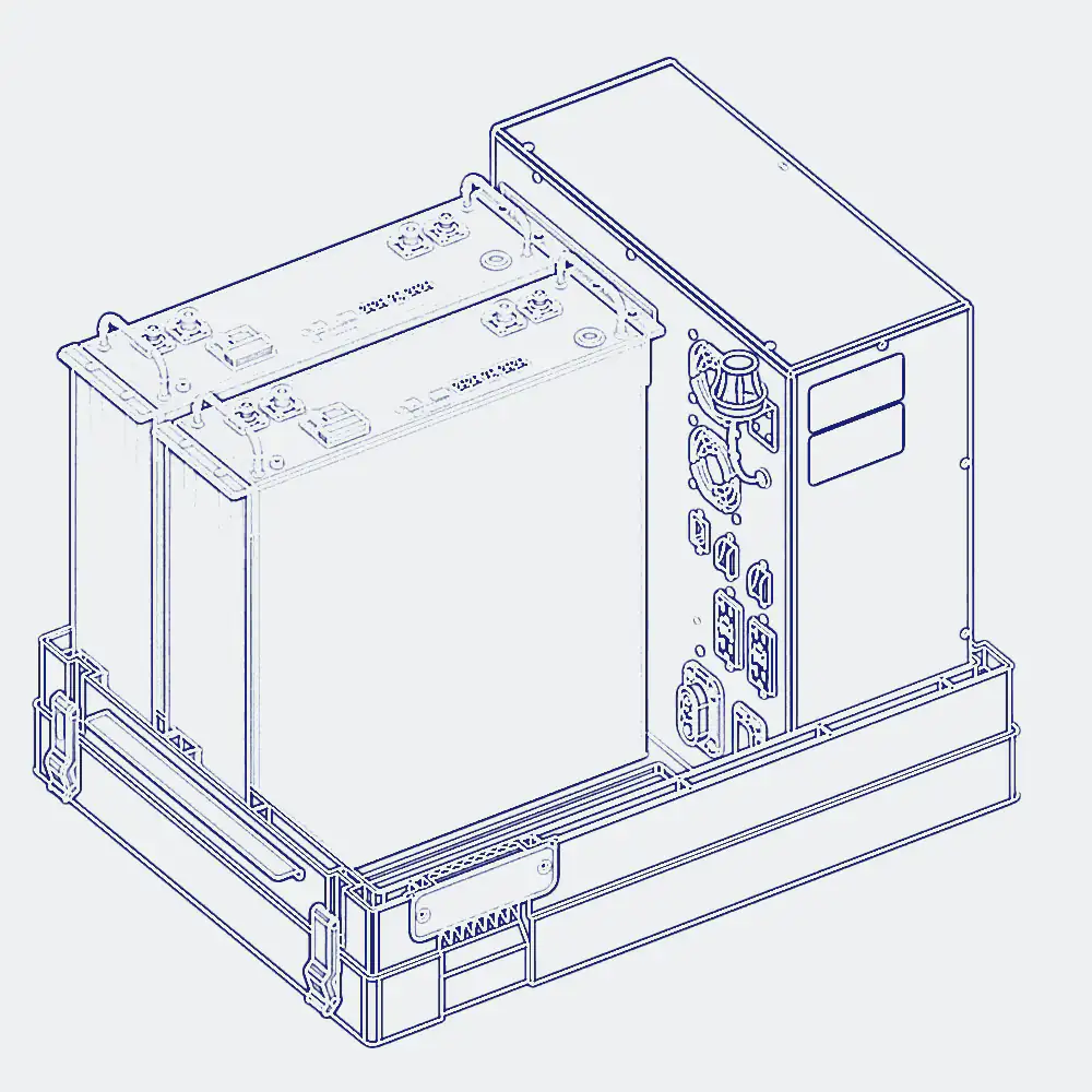
The second generation, which I lead, is a ground-up redesign: an integrated sheet-metal electronics enclosure carrying the inverter, battery modules, cooling, and wiring, packaged for weatherproofing, serviceability, and simple assembly.
Section D-D, Thermal, before
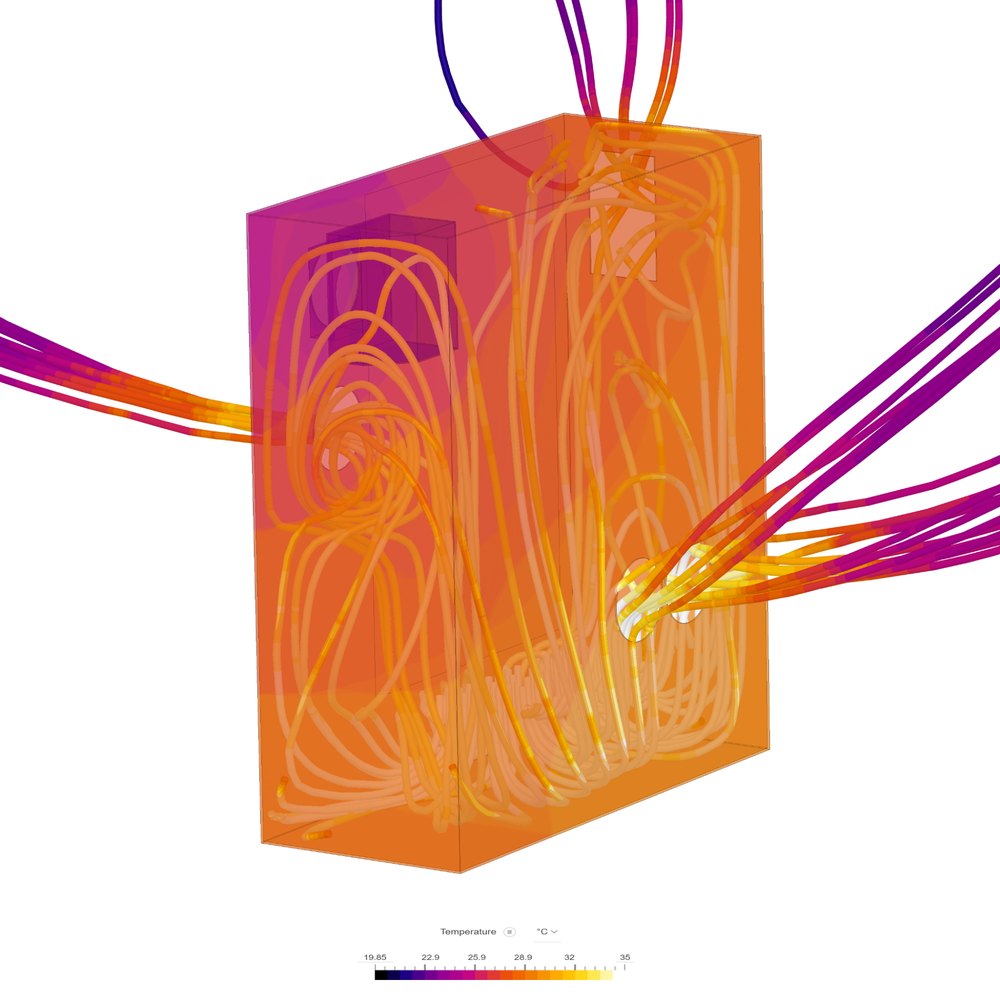
Where the heat was trapped
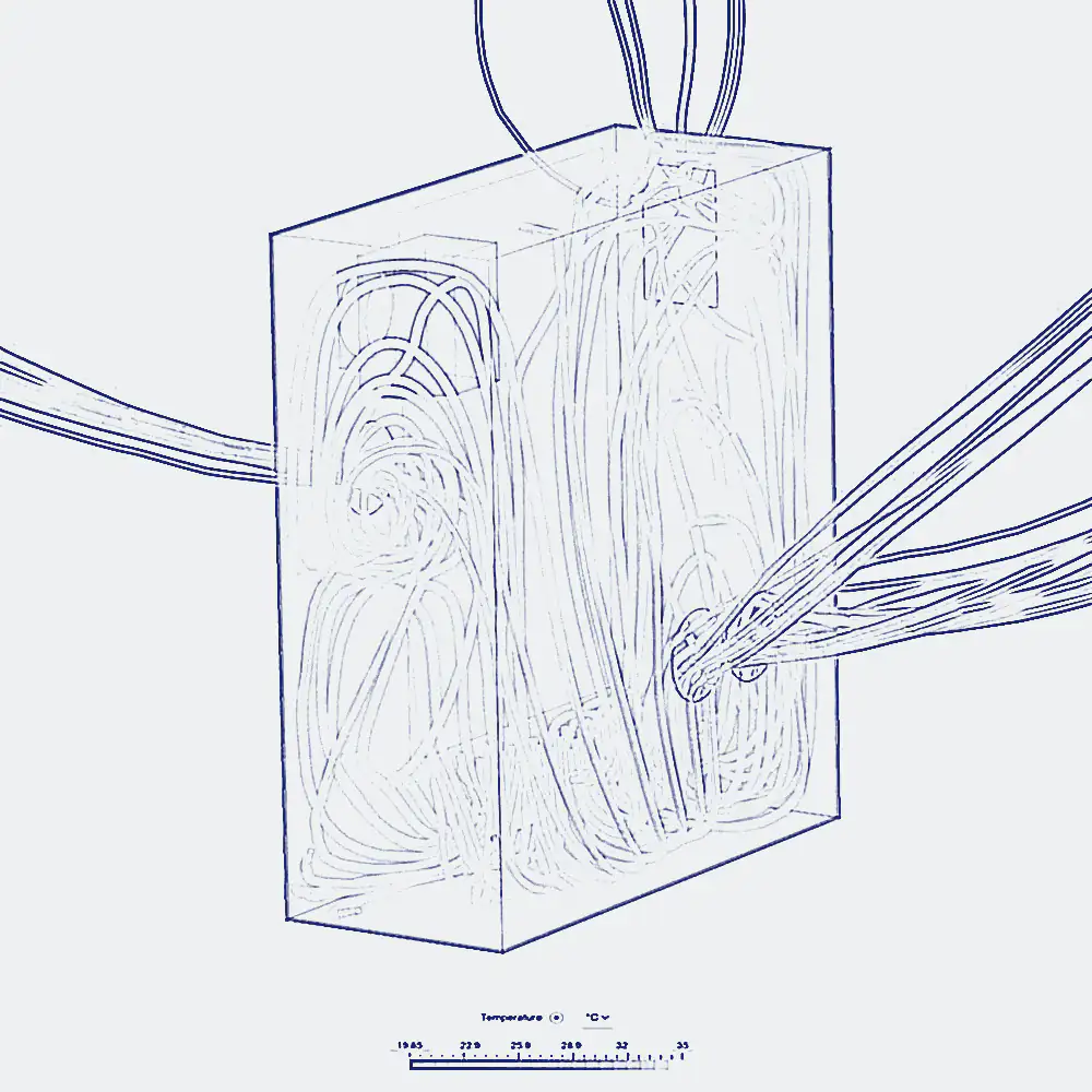
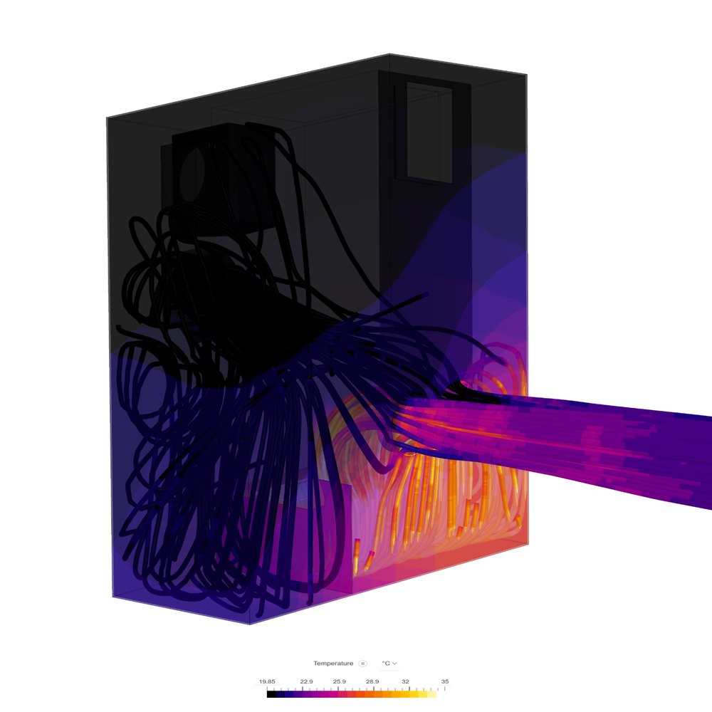
Initial CFD of the sealed enclosure under full inverter load showed hot air recirculating inside, with internal temperatures climbing well above ambient. The airflow was fighting itself.
Section E-E, Thermal, after
Cooled by design
Adding an internal baffle beside the inverter and a louver on the lower fan straightened the airflow path and cut recirculation. The optimized design holds roughly 11.6 C rise at the outlet and about 7.6 C at the most temperature-sensitive board, with rain- and sprinkler-proof inlets and outlets.
Section F-F, Structural (FEA)
Analyzed to lift and load
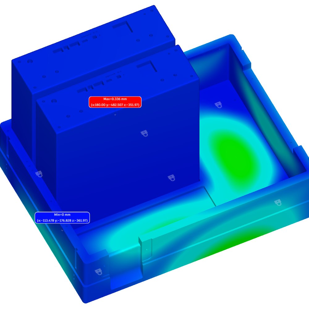
A full FEA campaign covered the load-bearing base under more than 100 lb of internal components and the molded-in lifting handles, with material trimmed for cost and weight while holding a strong safety margin, the production base reaching a safety factor above 100.